


VFD (VARIABLE FREQUENCY DRIVE) COMPLETE GUIDE
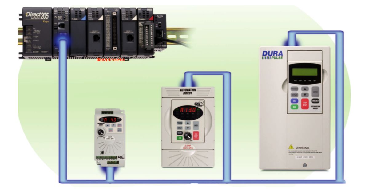
VFD is a widely used AC drive on the onboard ship. VFD comes with different power ratings based on the requirements. The higher the rating bigger will be the VFD.
In most of the cases, ETO is called for troubleshooting in case of any fault in VFD. In such cases, it is better to know the basics of VFD because troubleshooting begins from basic steps. In this post, we will discuss more about VFD.
Why to use VFD?
- Variable Speed and integrated functionality: AC drives can vary motor speed and direction by operator input (keypad buttons/speed control knob) or by digital and analog inputs (from pushbuttons/switches/pots or PLC outputs).
- Power Factor: Motors have very poor power factors (especially at light loading). Drives significantly increase power factor (even at light loading) and can eliminate the need for power factor correction capacitors and/or utility power factor charges.
- Reduce mechanical stress: controlled/smooth starting and stopping minimize mechanical shock and wear and tear on the system.
- Reduce start-up current: controlling the inrush current at motor start-up allows the use of smaller fuses, and reduces electrical peak load.
- Saves Energy: At low demand, the motor runs slowly and the power consumption decreases in proportion to the demand resulting in increased efficiency and energy savings.
There are certain application onboard where the motor has to run at lower speed, For Example, Cooling Sea Water pump which is not required to run at full speed when sea water temperature is reducing. Stopping pump is not a good solution but running pump at a lower speed can be the best option which also saves energy since the power consumption has reduced. Some application needs precise adjustment for best performance.
So this can be done with the help of VFD increasing/decreasing speed of a motor by varying frequency & voltage keeping the V/f ratio constant.
COMPONENTS & OPERATION
The basics parts of VFDs are Power Circuit, Control Circuit, HIM, Heat Sink & Power Supply Circuit.
POWER CIRCUIT
Power circuit consist of the following components as shown in figure
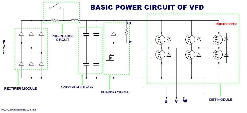
RECTIFIER MODULE: It is basically 3 phase rectifier that converts AC to pulsating DC. These diodes can handle high power. For safety varistor(surge suppression resistor) is connected to avoid damage to the rectifier module.
PRE-CHARGE CIRCUIT: Avoids inrush currents & allows the capacitor to charge slowly avoiding the capacitor getting damaged.
CAPACITOR BLOCK: This is also known as the DC bus in this system. It consists of capacitors connected in series & parallel combination.
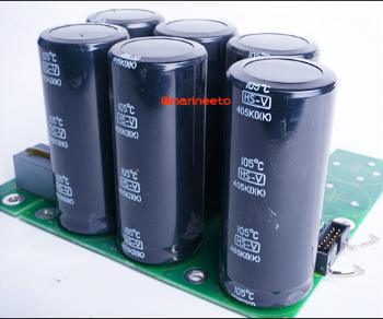
As we know the output of the rectifier module is pulsating DC which is above 600V DC for a supply voltage of 440V AC. Capacitor & Inductor work together as LC filters to remove AC components & produce pure DC.
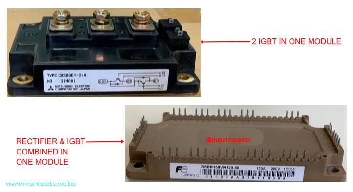
IGBT MODULE: IGBT (Insulated Gate Bipolar Transistor) is a high power 3 terminal electronic faster-switching device that has the advantage of BJT & MOSFETs. The module may consist of 2 IGBT in one module for 1 phase or 6 IGBT in one module for 3 phase AC. Freewheeling diode is connected to avoid IGBT getting damaged from regenerative power.
BRAKE CIRCUIT: This is for safety purposes. It consists of Braking Resistor, MOSFET as a switch. When there is the sudden discharge of regenerative power from the motor it can rise DC Bus voltage which results in damaging other components. This can be avoided by dissipating this regenerative power safely by switching MOSFET.
Braking resistors are also used to increase the control torque of the AC drive, for frequently repeated ON-OFF cycles of the AC drive, or for decelerating a load with large inertia.
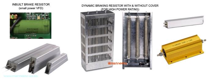
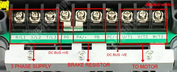
Braking Resistor connection is done at the terminal (i.e., B1 & B2). Small power VFD has an inbuilt brake resistor, VFD with a higher power rating requires a brake resistor connected externally.
MOSFET & IGBT triggering is carried by a control circuit, also it senses the voltage of the DC bus, some VFD power terminals consist of +DC bus & -DC bus terminals.
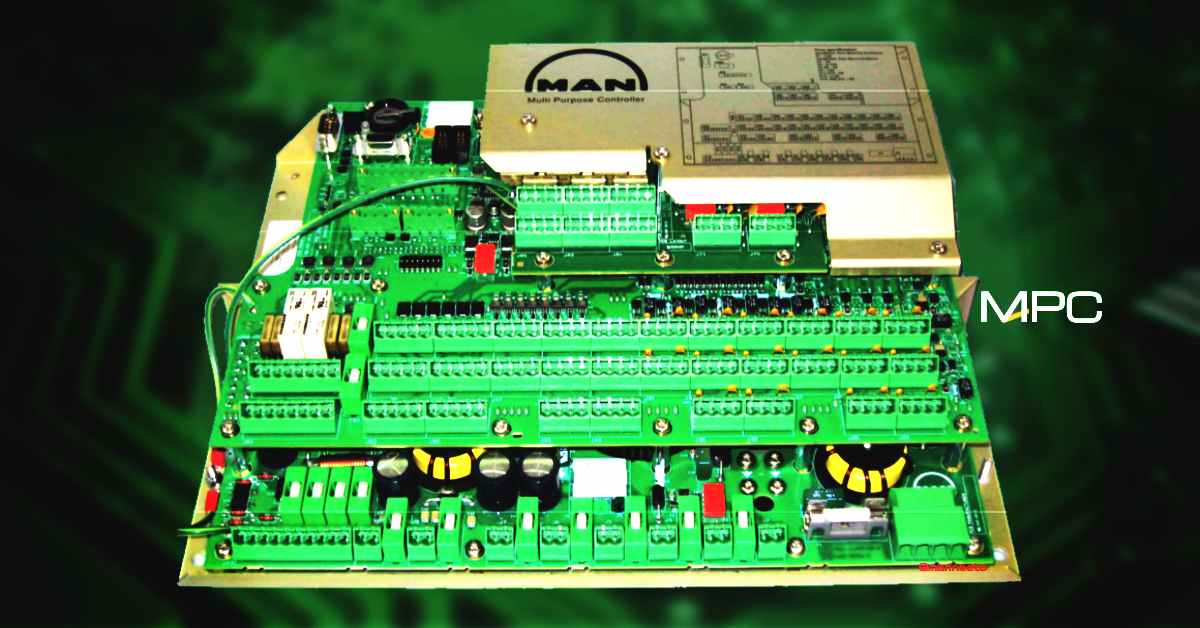
CONTROL CIRCUIT
The control circuit receives input/output, triggers IGBT. The Control circuit is connected to a programmable microcomputer in which parameters are set using a display & keypad.
The terminal of control circuit consist of as follows,
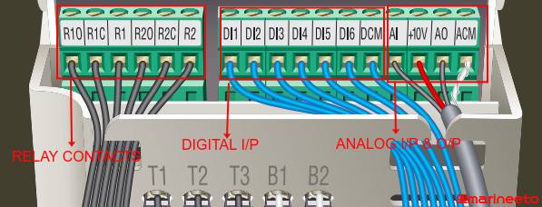
DI (Digital Inputs): commonly used to forward/reverse the direction of rotation of the motor from an external device by push button, relay contacts, PLC. Some times also labeled as LI (logic inputs)
DCM (Digital Common): ground terminal for Digital Input. If the DCM terminal is not available, the connection can be connected to the COM (common) terminal.
AI (Analog Input): some VFD uses 0-10V or 4-20mA for frequency scaling(for varying frequency from 0Hz to maximum). The input devices to AI are PLCs AO card, Potentiometer, etc.
AO (Analog output): output will AO terminal will be 0-10V or 4-20mA for external application.
ACM (Analog Common): ground terminal for the analog terminal else common terminal can be used.
R (Relay): this is NO NC contacts can be used for alarm, indication, or other applications. The relay can be read as R1C (relay 1 common), R10 (relay 1 Normally Open), R1 (relay 1 Normally Closed).
The high-end version of VFD also has DO (digital output), FO (digital frequency output), TH (for motor thermistor connection).
COMM PORT: VFD has a serial communication port to interface with devices like HMI, PLC, etc. Some VFD has RJ12 port, RJ45 port for MODBUS/CAN protocols.
NOTE: Every maker has its own keyword for labeling, but the function is almost similar. For Example: Durapulse VFD labels DI1 same function terminal is labeled as LI1 in Schneider Altivar VFDs.
HIM
Human Interface Module is a device attached to VFD with keypad, display & potentiometer which allows user to configure the drive, set the speed, start and stop the drive, and monitor critical parameters for your application.
FILTER
The input line reactor (filter) also reduces the harmonics associated with AC drives. Input line reactors are recommended for all installations.
Output line reactors protect the motor insulation against drive short circuits and IGBT reflective wave damage. Output line reactors also smooth the motor current waveform, allowing the motor to run cooler. The line reactor can be used for either input or output applications.
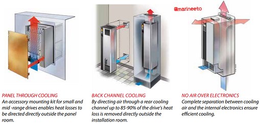
HEAT SINK
In order to dissipate heat efficiently from the rectifier & IGBT module heat sink is necessary. More the rating bigger will be the heat sink. Also, Fan is attached for better cooling and a Thermistor to monitor the temperature of the IGBT to avoid any damage to the IGBT.
NOTE: Every VFDs have its own programmable parameter which differs from maker to maker, model to model. So refer makers manual before altering any settings in VFD. The working principle & power circuit remains almost similar as described but there can be slight modifications, For Example: In some VFD Rectifier and IGBT Module comes with a single module.
TROUBLESHOOTING TIPS
If you have done restarting VFD, parameters are set as per application, the motor testing result is satisfactory but still, error code is displayed in the VFD display below few troubleshooting tips can be carried out. (refer error codes in manual provided)
| PROBLEM: HIGH TEMPERATURE |
| CAUSE: Faulty cooling fan, Choked air filters, Dirty heat sink, Faulty temperature sensor |
| ACTION: Check fan rotating or not? if not check the fan power supply if the power supply is ok, then replace the fan. Cleaned choked air filters or replace the filter. Clean the dirty heat sink with approved solvents or CRC. Replace the faulty temperature sensor. contact maker for technical assistance if problem not resolved. |
| PROBLEM: UNDER VOLTAGE |
| CAUSE: No or less DC bus voltage, Phase loss |
| ACTION: Check DC bus voltage must be above 600V for 440V AC supply (√(2) multiplied by supply voltage under no running condition i.e., √(2)x440=622V DC. Check for a blown fuse, faulty contactor/breaker for missing phase at the input. Check capacitor banks are bulgy/leaking. Perform static checks If the above checks are satisfactory there might be a problem with Undervoltage IC/control circuit, contact maker for technical assistance. |
| PROBLEM: OVERVOLTAGE |
| CAUSE: Faulty braking resistor, Power surge |
| ACTION: Check braking resistor, Also check input power & DC bus voltage Perform static checks. If able to identify MOSFET check it else contact maker for technical assistance if the problem not resolved. |
| PROBLEM: OVERCURRENT |
| CAUSE: Motor overload, False alarm |
| ACTION: Check the overload settings, measure current manually. contact maker for technical assistance if problem not resolved. |
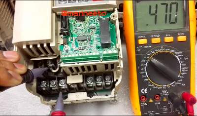
STATIC CHECKS
- Put DMM in diode mode, To perform the test at the input section (R, S, T) with +DC bus, Place DMM lead +ve probe at R and -ve probe to +DC bus terminal. For a healthy diode, the reading must show 0.4 to 0.6V, repeat the step for the other two-phase, the reading must match more or less the same. Reverse polarity of probe reading must show OL (open) for all phases.
- Similarly perform the test at the input section (R, S, T) with -DC bus.
- For Short diodes the reading may show less than 0.1V, Similarly for open diode DMM reading may show OL (Remember your DMM can measure 0-1V in diode mode).
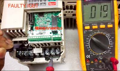
- Similarly perform the test in the output section (U, V, W) with +DC. Put DMM in diode mode, Place DMM lead +ve probe at U and -ve probe to +DC bus terminal. It shows 0.4 to 0.6V same reading of diode, repeat the step for the other two-phase, the reading must match more or less the same. Reverse polarity & check it should show OL, else the IGBT is faulty. Also, perform the test with -DC bus.
NOTE: If DC bus terminal absent in VFD open front cover to identify +VE & -VE DC bus in PCB.
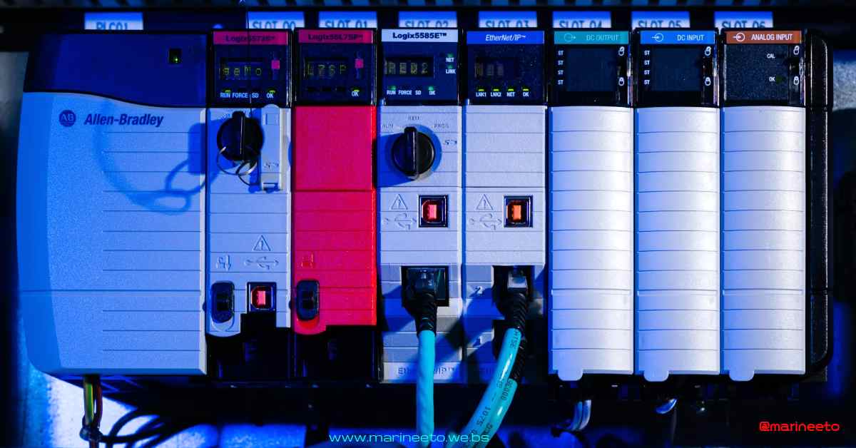
ALSO READ PLC click here
REFERENCES
- VFDs https://vfds.com/
- Voltage Disturbance https://voltage-disturbance.com/
LIKE POST? PLEASE SHARE

great explanation for VFD.. WORTHY APP
Thank you Edwin Shinal Roy.
Keep supporting us
bien
thanks for this post, it’s really helpful. Nice post abhilash
thank you keep supporting us
it’s good for upgrading ETO students knowledge..thank u